DiscoverHover CURRICULUM GUIDE #7
THRUST
© 2004 World Hovercraft Organization
So far we’ve discussed how pressurized air beneath the hovercraft causes
it to hover, and we investigated what happens when hovering over water. We also
looked into some of the drag forces encountered when moving through water. Let’s
examine how a hovercraft’s forward motion is produced. A hovercraft moves
by using air to create forward thrust. The propeller
on the back of the Discover Hover One forces air towards the rear. How does
forcing air behind the hovercraft produce forward thrust? Remember Newton’s
third law: Every action has an opposite and equal reaction. The propeller
exerts a force on the air when it pushes it behind the hovercraft. The air,
in turn, exerts a force back on the propeller in the opposite direction. This
causes the propeller, as well as the rest of the hovercraft, to be accelerated
forward.
When designing propeller systems for hovercraft, efficiency is a big concern.
Efficiency is the ratio of how much work is produced
divided by how much work is put into the system. In order to produce forward
thrust (the output), we must power the propeller with a fuel-driven engine (the
input). Engineers try to get as much output work as possible for the least amount
of input work. Unfortunately, you can never get out as much work as you put
in. The heat produced by the engine, the noise produced by both the engine and
the propeller, and the vibrations you can feel in the hull are just some examples
of wasted energy that isn’t being used to produce thrust.
One way to increase the efficiency of a propeller is by surrounding it with
a circular enclosure called a thrust duct. In a small
hovercraft, a properly built thrust duct can add a 10%-15% increase to the total
thrust output, compared to a non-ducted propeller.
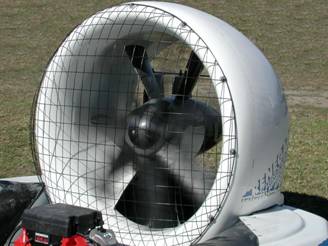
Example of a hovercraft thrust duct
To function properly, a thrust duct must be of an aerodynamic shape and smooth
on the inside. The propeller tips should be no more than 1/8 of an inch [0.3175
cm] away from the inside wall. If there is too much space between the thrust
duct and the propeller tips, the air will move from the back of the blade (higher
pressure) to the front of the blade (lower pressure). This reduces the fan or
propeller efficiency because it causes turbulence. The closer the propeller
tips are to the wall of the duct, the more efficient they become. A typical
propeller can produce 4 - 6 lb [17.79 – 26.69 N] of thrust per horsepower,
or 23.8 – 35.8 N/kW. The length of a thrust duct is also important. Air
resistance caused by the air dragging against the walls of the thrust duct as
it is blown back will increase as the length of the thrust duct increases, causing
the thrust output to decrease. A typical duct is 18 inches [45.7 cm] long, with
the propeller positioned 7-8 inches [17.8-20.3 cm] behind the front bell mouth
edge of the duct. This allows the propeller or fan to pull air into the thrust
duct, compress it, and push it out of the rear of the duct.
According to Newton's second law, thrust can be calculated by multiplying the
mass of the hovercraft by its acceleration. We can determine the acceleration
of the hovercraft using the formulas we learned in Curriculum Guide #2. Remember
that a hovercraft is affected by different drag forces depending on the surface
it's flying over. When you calculate a particular thrust, it is for that particular
situation you tested the craft in. Remember that for a fan or propeller, the
thrust force decreases as forward speed increases!
This is because as the speed of the hovercraft increases, so does the speed
of the air that enters the thrust duct. It’s harder for the propeller
to accelerate air that’s already moving fast, so it is unable to produce
as much thrust at higher speeds.
MEASURING THRUST
Probably the most accurate way of measuring hovercraft thrust is via a strain gauge force measurement setup, however a reasonably accurate measurement can be made with a spring balance (butchers scale) provided some common sense precautions are made.
- Select a flat smooth concrete or similar surface, away from ambient winds of more than 5mph velocity, to carry out the measurement.If there is any suspicion that the surface is not really flat (less that say 1/2% gradient) then measurements will have to be made in two directions, one up slope and one down slope.
-
Fasten the spring scale to a secure pole, bollard or similar object at one end and the hovercraft tie down cleats at the other via a light weight rope or cable. If the spring scale has significant weight then it should be fastened to the pole end and not the craft end of the tackle. when the craft is on-cushion and under tension the rope should be perfectly horizontal to the concrete floor to avoid lifting or pulling down the rear of the craft.
-
With a pilot or weight in the craft, positioned so as the craft is perfectly trimmed when on cushion thrust measurements can commence. To ensure trim a carpenter's bubble level can be positioned on the cockpit floor and pilot or weight can be moved fore or aft until the level bubble is centralized.
-
Take thrust readings at several engine speeds - say 4,000 rpm, 5000 rpm, 5,500 rpm and full throttle rpm. At each speed record RPM and thrust after readings stabilize. It is recommended that the spring scale be pulled back slowly until craft moves backward slightly and another thrust reading taken. This is after the static reading has been recorded and can be done by hand or winch. This procedure will compensate for any skirt drag that may be present.
-
If there is any slope or wind at the test site, the test must be repeated with the craft facing in the opposite direction. Do not attempt to conduct thrust tests on rough surfaces such as grass or gravel or on a windy day as accurate results will be impossible to obtain.
-
Plot rpm vs. thrust results obtained on graph paper or graphics computer screen and see if a relatively smooth progression is indicated. If there are any sudden jumps or dips in the trace it probably means an error in measurement or technique.
Continue to Experiment
7.1