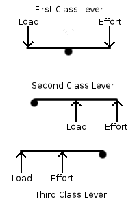
Figure 21-1: The three classes of levers
Image ©2006 DiscoverHover
| NAME | DATE |
Hovercraft are fairly complicated machines, but, like most mechanical devices, many of their parts consist of a few simple machines that are used to change the direction or magnitude of applied forces. When the magnitude of an applied force is changed by a simple machine, it is said that the machine gives a mechanical advantage. The mechanical advantage is the ratio of the force exerted on the load to the force put into the machine. In an ideal machine, the work put into the machine would equal the work coming out, and since work is the product of the force and the distance, the ratio of the distances would be the reciprocal of the ratio of the forces. However, due to friction and due to the mass of the machine itself, the ideal mechanical advantage (IMA), the ratio of the input distance to the output distance, is usually less than the actual mechanical advantage (AMA), the ratio of the output force to the input force. The efficiency of the machine is the ratio of the work put out to the work put in.
IMA = xin / xout
AMA = Fout / Fin
Efficiency = Wout / Win = (Fout × xout)
/ (Fin × xin)
Examples of simple machines are the lever, wheel, inclined plane, pulley, screw, and wedge.
Figure 21-1: The three classes of levers
Image ©2006 DiscoverHover
Levers work is through the concept of torque. Remember that torque is proportional to the distance from the center of rotation. Applied force exerts a torque around the fulcrum based on the distance between them, and that is transferred to the load, which is at another distance from the fulcrum and therefore has another magnitude of the force acting on it. The other effect a lever has is to reverse the direction of the force. If the two lever arms are of equal length, the forces on them will be equal in magnitude and opposite in direction. One thing to note is that in the third-class lever or in a first-class lever where the effort arm is shorter than the load arm, the effort force is considerably greater than the output. This seems to be the opposite of what simple machines are supposed to do, but remember the “side effect” of simple machines: the ratio of the forces is the inverse of the ratio of the distances. Since both forces are constrained to move with the same angular motion, the linear motion of the longer side is faster. For accelerating objects that are not very massive compared to the input force, it is often advantageous to increase the speed rather than the force. There is a location on a hovercraft where third-class levers are extremely important: the blades of the propeller all rotate around the point at the center of a shaft, each converting a large central force at the base of the blade into a faster and less forceful motion at the tip.
Think about how the propeller on a hovercraft consists of some number of levers all rotating around a single fulcrum. With more or wider blades, more area is covered, although each lever still has the same behavior as it would on its own. If you had a large enough number of wide enough levers of the same length, it would be a solid circle rotating around a point. This is commonly called a wheel. A wheel is a circular lever where the fulcrum is called an axle, one arm is the radius of the wheel, and the other arm is the radius of the axle. Wheels are often used in transportation as a method to avoid the friction inherent in sliding a vehicle along the ground (the amount of sliding is based on the circumference of the axle rather than on the ground contact area). No doubt you will have noticed by now that the DiscoverHover One has no wheels, but there are plenty of other uses for the wheel. Gears, flywheels, gyroscopes, and most pulleys use wheels as well, so there are plenty of applications. The IMA for a wheel is the same as for a lever, although a wheel can act as any of the three classes of lever, depending on where the load and effort are applied. Figure 21-2 illustrates the three configurations of the wheel. The first-class configuration is used in pulleys, the second class in winding, and the third class in a fan, propeller, or bicycle wheel.
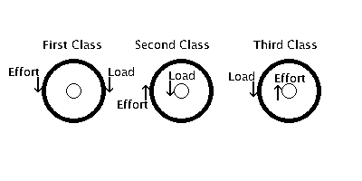
Figure 21-2: Similarities between wheels and levers
Image ©2006 DiscoverHover
Another simple machine is the inclined plane. This is a simple device consisting of a surface that is steeper than level ground but not as steep as a vertical wall. The IMA of an inclined plane is the ratio of the displacement (A in Figure 21-3) along the plane of the moving object to the component of that motion in the intended direction of motion (B in Figure 21-3).

Figure 21-3: IMA of an inclined plane
Image ©2006 DiscoverHover
This simple machine is very useful for your DiscoverHover One, since hovercraft are unable to fly vertically. Rivers are lower than their banks, so a hovercraft has to move upward to transition from water to dry land. The mechanical advantage offered by an inclined plane, such as a beach or boat ramp, makes this possible.
A pulley is another common simple machine, consisting of a rope (or something similar, such as a string, chain, cable, or belt) that is free to move across an object that changes its direction. This is almost always a wheel due to the friction inherent in sliding the rope across the pulley. When you pull a shoelace through a hole and use it to pull the shoe closed, the hole is a movable pulley. The mechanical advantage of a pulley system depends on the number of pulleys in the system.
|
|
||||
|
|||||
| (c) | |||||
|
Figure 21-4: Different pulley configurations Image ©2006 DiscoverHover | |||||
To illustrate this, consider a case where a 512 N [115.1 lb] load is being moved upward 2 m [6.56 ft] in a room with rafters across the ceiling. To lift the load with no pulley, you would have to stand on a rafter and pull 2 m [6.56 ft] of rope upwards with 512 N [569.37 newtons] of force as in Figure 21-4 (a). If you added a pulley to the ceiling, you could stand on the floor and pull down, as shown in Figure 21-4 (b), but you would still be pulling 2 m [6.56 ft] of rope with 512 N [115.1 lb] of force. If you add a pulley to the load and attach the end of the rope to the ceiling instead of to the load, then the load is supported by two lengths of rope, as shown in Figure 21-4 (c). Since the load still weighs the same, the load on each section of rope, including the one you hold, is now only 256 N [57.55 lb]. When you pull 2 m [6.56 ft] of rope, the length is divided between the two segments holding up the load. By pulling the rope 2 m [6.56 ft], the load will move 1 m [3.28 ft]. To move the load 2 m [6.56 ft], you would have to pull 4 m [13.12 ft] of rope. More pulleys can be used, in a configuration known as a block-and-tackle. In this, pulleys are arranged in parallel blocks as in Figure 21-5. In this diagram, (a) shows four pulleys separately for clarity, and (b) shows an alternative arrangement. The IMA of a block-and-tackle system is always a whole number, since it is equal to the number of ropes supporting the load.
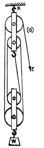

Figure 21-5: Block and Tackle
(a) Image courtesy Basic Physics, 8th ed., Volume 1, by A.R. Mott
(b) Image ©2007 DiscoverHover
If two inclined planes are arranged as in Figure 21-6, then the resulting simple machine is called a wedge. A single inclined plane can also be a wedge, the distinction between a wedge and an inclined plane is that with an inclined plane it is the load that moves along the slope, whereas a wedge is usually moved in order to exert a force on the load perpendicular to the motion of the wedge. Wedges are used to separate either two objects from one another or one object into two parts, or to hold objects in place. Examples of wedges in everyday life are axes (that split wood), doorstops (that push against the door and floor), and scissors, saws, files, chisels, and the like (the blades separate parts of a material). Some hovercraft have pointed ends that act as wedges to part the water and air in front of them, which can make going through waves and air easier and smoother. Propeller blades also act as wedges, pushing the air as they move around.

Figure 21-6: Wedge
Image ©2007 DiscoverHover
The primary drawback to using an inclined plane to effect the motion of an object from one point to another is that it takes up a large amount of space to get a significant mechanical advantage. If the inclined plane is “wrapped” around a circular base, as shown in Figure 21-7, lateral space can be reused many times because each successive turn is elevated relative to the previous turn. Since the plane can be supported by the central body, there is no need to support it from below. Screws are used for fastening objects, where the rotation of the screw causes the incline to move, exerting a force on the screw to move it into (or out of) a material. Another famous screw is the Archimedean Screw, which uses a large screw enclosed in a cylindrical tube to move water or other fluids from one place to another. Fastening screws are used in many places on hovercraft.
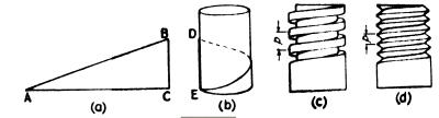
Figure 21-7: Formation of the Screw
Image courtesy Basic Physics, 8th ed., Volume 1, by A. R. Mott
As you can see, simple machines provide a way to convert an input energy to a work output. Friction always decreases the efficiency of a simple machine, although it is necessary for the operation of some. For example, a screw would be useless without friction because it would just slide out after being screwed in. Wheels on vehicles would spin in place, and a doorstop would slide out and let the door close. Another characteristic that affects real machines is the mass of the machine itself. In a block and tackle, the weight of the moving pulleys is an added load if it moves upward. Conversely, in a first-class lever where the effort arm is longer than the load arm, not only does the mechanical advantage decrease the force to lift the load but, if the bar is uniform, then the weight of the bar will contribute to the input. This might seem to indicate that it it possible to put out more work than is put in, because the active agent would, in fact, have to exert less force. However, work has to be expended lifting the lever bar into a working position. The work done on the load through a simple machine is the product of the force exerted and the distance over which it acts. This is the same as when work is done directly on the load, and is the principle behind the fundamental trade in simple machines between the magnitude of the force and the distance. Since the power is the capacity for doing some amount of work over a span of time, simple machines can allow a relatively weak force to perform work with a significant speed of operation.
Another way to look at simple machines is to view them as ways to convert mechanical energy from one type to another, from one object to another, or both. For example, a rotating wheel converts an angular kinetic energy at the axle into a linear motion at the edge of the wheel. The classic example of a first-class lever, where a weight is dropped on one end to send another object into the air, converts gravitational potential in the weight into an upward kinetic energy in the object. The principle of conservation of energy states that the total amount of energy in a system cannot change, which is why the work put out has to equal the work put in, with frictional losses taken into account.
Quiz Question:
| ©2005 World Hovercraft Organization All rights reserved. Copies of this Curriculum Guide may be printed for classroom use exclusively by DiscoverHover registered members. This Curriculum Guide and all materials contained in the DiscoverHover web site are protected by copyright laws and may not be reproduced, republished, distributed, or displayed on any other web site without the express prior written permission of the World Hovercraft Organization. |


