Figure 26-1: Anatomy of a wave.
Image ©2007; DiscoverHover
| NAME | DATE |
Hovercraft operate mostly over water, which is often rough. Rough water is caused primarily by wind as it blows over the water. Hovercraft also produce considerable sound waves.
Waves are based on the principle of oscillation, where the particles that make up the wave move back and forth across a natural position for each particle. There are two ways to explain these oscillations and therefore, two types of waves: transverse waves and longitudinal waves. In a transverse wave, the particles move perpendicularly to the direction in which the wave moves. Examples of transverse waves are ripples in ponds, waves running along strings, and stadium waves. A transverse wave requires that the medium have elasticity — the particles affect their neighbors as they move up and down, otherwise the wave would be unable to propagate. In the example of pond ripples, it is the surface tension on the water provides the elasticity, in the string, it is the tension of the string; and in the stadium wave, it is the people ahead of the wave who see it coming and decide to participate. The medium can be any of a number of things, such as water, air, oil, or even a vacuum. The crest or peak of a transverse wave is when the particles of the wave are at their highest point; the trough is when the particles are at their lowest point. In the other type of wave, a longitudinal wave, the particles oscillate in the same direction as the wave travels. The prime example of this is sound waves, in which particles of air oscillate and push each other; the same action occurs in other materials such as water, helium, or rocks. This means that the particles in longitudinal waves are capable of propagating through fluids, whereas the particles in transverse waves simply move up and down relative to the particles near them. The motion of the particles in a longitudinal wave results in moving regions of relatively high pressure separated by lower-pressure regions. The high-pressure regions are compressions and the low-pressure regions are rarefactions. When waves in water are larger than the ripples on the surface of a pond, the wave motion is of a third type, referred to as a surface wave, in which the particles move in a the manner of both transverse and longitudinal waves and the motion forms circles. This behavior only occurs in the molecules near the surface of the water. For molecules deeper below the surface, the circles become smaller and flatter until they are small longitudinal displacements at a depth approximately a third of the wavelength of the wave.
In any mechanical wave, there are several quantities that describe the wave. Wavelength (λ) is the distance from one point on the wave to the analogous point on the next oscillation of the wave, for example, the distance between two crests. Displacement of a particle in a wave is the distance of a particle from its natural position line of the wave at a certain time. The amplitude of a wave is the maximum displacement of the particles in the wave, the height of the crests in a transverse wave or the distance the particles in a longitudinal wave travel before moving back to their original position. The frequency of a wave is the number of oscillations the particles make in a certain amount of time, where each particle goes through one complete cycle and returns to the same position and velocity at which it started. Similarly, the period of a wave is the time it takes for the wave to complete one oscillation. These quantities sometimes have specialized names for specific types of waves. For example, the amplitude of a sound wave is also known as loudness; the frequency of a sound wave is also known as pitch (musical notation is based on a value of 440 Hz for the A above middle C); and wavelengths of light is the color (most people can see colors from a red approximately 7000 Å (2.756×10⁻⁵ in.) to a violet approximately 4000 Å (1.575×10⁻⁵ in.)).
Figure 26-1: Anatomy of a wave.
Image ©2007; DiscoverHover
The wave relationshipis an equation that relates some of these parameters to each other.
v = f × λ
The velocity v with which the wave propagates is the product of f (the frequency of the wave) and λ (the wavelength). Waves travel at different speeds through different media due to the physical characteristics of the medium. The frequency of a wave is determined by the source and does not change in different media, so the only property that can change is the polarization.
When two waves encounter each other at a certain point at a certain time, they interact in what is called interference. Interference means that the amplitudes of the waves add together when they are in the same place at the same time. This is the Principle of Superposition. If two waves are equal in amplitude and wavelength, and the troughs and crests of each wave line up with those on the other wave, then the two waves will add to form a wave equal in wavelength to, and double the amplitude of, each of the constituent waves. This is known as constructive interference. If the same two waves interfere, but the troughs on each correspond to the crests on the other, then the addition of the waves will result in a wave of zero amplitude — a flat line. This is called destructive interference.
Figure 26-2: Interference Types — constructive above and destructive below.
Image ©2007 DiscoverHover
Mechanical waves, as we have seen, result from the oscillation of particles within a medium. Another type of wave differs from mechanical waves in that the propagation of the wave results from movement of the particles themselves. There are electromagnetic waves and include light, which refers to the narrow range of wavelengths that are visible to most humans. The particles that oscillate to make electromagnetic waves are photons, and they travel at the speed of light. Electromagnetic waves are composed of two transverse waves at right angles to each other along the axis of propagation. The quantities that oscillate are electric fields and magnetic fields.
Another form of electromagnetic radiation is radio waves, which are important in machines such as hovercraft because they are produced by some electrical components and can interfere with the operation of others. Another form of wave that is relevant to hovercraft is sound, which is produced by hovercraft engines, propellers, and fans. As with any internal combustion engine, some noise can be reduced by adding mufflers to the hovercraft. Inside the muffler, sound waves are reflected through a chamber known as a resonator. This chamber is designed so that the waves reflecting off the walls interfere with each other to cancel the sound. Surface waves, which occur in bodies of water, are also relevant to hovercraft. Hovercraft frequently operate over water, and water waves can significantly affect their motion while in operation.
There are certain behaviors that are common to all waves: they can all undergo reflection, refraction, diffraction, interference, and the Doppler effect. We have previously discussed interference; let us now explore the remaining wave behaviors in turn.
Reflection is an important wave behavior, and is possibly the most directly apparent in its effects. In light waves, reflection makes it possible to see objects; in sound waves, reflection is responsible for echoes; water waves are seen when they rebound (reflect) off of the edges of a sink, swimming pool, or ocean. An interesting wave reflection occurs when pressure waves in the cushion of a hovercraft reflect off the bed of a body of water over which the hovercraft is traveling. If the water is of a certain depth, then the pressure wave reflected off the solid surface will interfere with the lift air cushion, causing the hump (or wave-making) drag to be considerably higher than it is at other depths. Reflection is based on the simple principle that the direction in which a wave is reflected is at an angle equal to that at which it contacted the surface.
Figure 26-3: Reflection at a boundary.
Image ©2007 DiscoverHover
Refraction is another effect of wave motion, usually observed in light waves. The principle behind refraction is that waves propagate at different speeds in different materials. If a wavefront approaches a boundary between two materials at an angle, the portion of the wavefront closest to the boundary will change in speed sooner than the portion of the wavefront that travels further in the first medium. A simple way to picture this is to imagine a wavefront consisting of two particles, for example, a little cart with a wheel on either side. If the cart travels at an angle from a hard sidewalk to grass, the first wheel to strike the grass will slow down due to friction while the second wheel continue at the same speed, causing the cart to turn at a steeper angle, as shown in Figure 26-4 (a). This phenonemon can also be observed in hovercraft transitioning from water to land. If the cart is better suited to grass than sidewalk, then the first wheel to hit the grass will speed up sooner, so the cart will continue at a shallower angle, as in Figure 26-4 (b). If the cart travels equally well over both surfaces, it will continue on its original course.
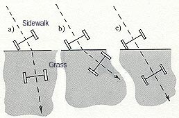
Figure 26-4: Wavefront path of refraction at a boundary.
Image ©2007 DiscoverHover
An excellent example of wave refraction is the bending of light waves when they pass from air to water. A stick placed across the boundary will appear broken or bent. This refraction is described by Snell’s Law, which states that the ratio of the sines of the angles at which a light ray approaches and leaves an interface is given by the inverse ratio of the indices of refraction of the two media.
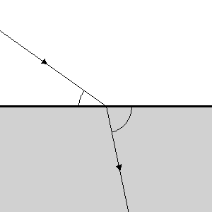
Figure 26-5: Ray path of the refraction at a boundary
Image ©2007 DiscoverHover
Another interesting, but less common, example of refraction is when, in early morning, the sun warms the upper air over a lake so that is warmer than the air near the ground. In this situation, many of the sound waves that would otherwise be lost into the sky are refracted due to the faster speed of sound in warmer air, and form, in effect, a natural amplifier.
Figure 26-6: Wavefronts of the sound wave
Image courtesy Georgia State University,
http://hyperphysics.phy-astr.gsu.edu/hbase/sound/refrac.html
Another form of refraction is in water waves: the speed of water waves is proportional to the depth of the water, so when a wave passes from deeper water to shallower it will change its direction.
Diffraction is a feature of waves wherein a wavefront encountering an obstacle bends around the obstacle in certain ways. For example, a water wave can encounter a buoy and will bend around the buoy in such a way that after a few wavelengths it will be as though there were no obstacle. Another example of diffraction is the manner in which sound waves bend around the corners when passing through a doorway. If this diffraction did not occur, it would be impossible to hear sounds in another room unless you were standing in the doorway. A third example of diffraction, a favorite in science classes, is when a beam of light passes through a small slit. The light spreads out from the slit due to diffraction and the parts of the beam diffracting from the two sides of the slit interfere with each other to form light and dark bands.
Christian Johann Doppler
1803 – 1853
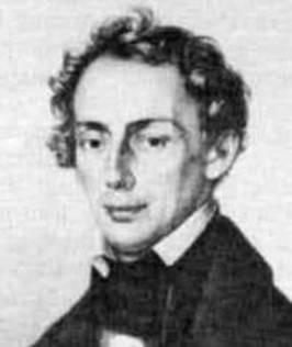
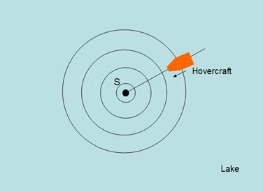
In 1842, Christian Johann Doppler called attention to the fact that the frequency of a sound seems to vary when the source or the observer is moving relative to the other. The frequency of the sound is higher when an observer moves toward a stationary source, the source moves towards the stationary observer, or when they move towards each other. This is illustrated in the figure below. On the left we have a stationary source producing a sound with frequency f, and on the right we have a source of frequency f, moving with velocity vs towards the right. We have two observers who are both stationary. The observer on the left hears a sound of frequency f from the stationary source and hears a sound of lower frequency from the moving source. The observer on the right hears a sound of higher frequency from the moving source and hears the same frequency f from the stationary source.
Figure 26-7: Change in frequency heard by a moving source.
Image courtesy Georgia State University,
http://hyperphysics.phy-astr.gsu.edu/hbase/sound/dopp.html
The frequency of the source heard when the source is approaching a stationary observer is:
fobserved = fsource × v / (v − vs)
where v is the speed of sound in the medium through which the sound is traveling. When the source is receding from the stationary observer the frequency heard is:
fobserved = fsource × v / (v + vs)
When the observer approaches a stationary source, the frequency heard is:
fobserved = fsource × (v + v0) / v
When the observer is moving away from a stationary source, the frequency heard by the observer is:
fobserved = fsource × (v - v0) / v
When the observer and the source are both moving away from each other, the frequency heard by the observer is:
fobserved = fsource × (v - v0) / (v + vs)
When the observer and the source are moving towards each other, the frequency heard by the observer is:
fobserved = fsource × (v + v0) / (v - vs)
When the observer is moving away from a source which is moving towards the observer, the frequency heard by the observer is
fobserved = fsource × (v - v0) / (v - vs)
| Example 1: A stationary siren (source S) in a lake generates a sound of frequency 330 Hz. To investigate the source of the sound, a hovercraft travels with a velocity of 10 m/s [22.36 mph] towards the stationary source. What will be the frequency observed by the pilot of the hovercraft if the speed of sound in air is 330 m/s [738.19 mph]? Solution:
We see that the pilot of the hovercraft is approaching the stationary source, so the frequency heard by the pilot is given by: fobserved = fsource × (v + v0) / v fobserved = 330 Hz × (330 m/s [738.19 mph] + 10 m/s [22.36 mph]) / 330 m/s [738.19 mph] Therefore, the frequency observed by the hovercraft pilot is 340 Hz. |
Another feature of waves, notably electromagnetic waves, is a phenomenon called polarization, which is a description of the direction in which the particles in a wave vibrate in a particular direction perpendicular to the direction of propagation. Obviously, this is a property of transverse waves only, since the carriers of longitudinal waves do not move perpendicularly to the wave motion. Normally, light sources, such as the sun, produce unpolarized light, meaning that the photons are all vibrating in different directions. When light reflects off a surface or passes through a polarizing filter, the photons that are not vibrating in a certain direction are absorbed from the beam, resulting in light that is polarized in a single direction. A polarizing filter can polarize light in any direction depending on the orientation of the filter, whereas light reflecting off a surface will be polarized parallel to the surface. For example, sunlight reflecting off water will be horizontally polarized.
Polarized sunglasses use this same property to block glare from the ground while minimizing the diminishment of brightness in the rest of the field of view. The material in the glasses is a vertically-oriented polarizing filter, so it blocks all horizontally-polarized light. Most light is scattered at all angles, so polarized sunglasses halve the light intensity when they remove the horizontal components. Reflected glare, however, is completely negated since it is horizontally polarized. This explains why wearing polarized sunglasses makes it easier to see objects under the surface of the water, as shown in Figure 26-9
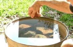
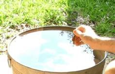
Figure 26-9: View with and without polarizing filter
Images courtesy polarization.com,
http://polarization.com/water/water.html
Sir Francis Beaufort
1774 – 1857
The Beaufort Scale was one of the first scales to estimate wind speeds and their effects over water. Britain’s Admiral Sir Francis Beaufort developed the scale in 1805 to help sailors estimate winds via visual observations. The scale measures from 0 to a force of 12. The Beaufort Scale is still used today to estimate wind strengths and wave heights. In its original form as applied to large warships of the late 18th and early 19th century, force 0 through force 4 on the scale describe wind in terms of the speed with which it would propel the ship under full sail. Forces 5 through 9 describe the wind in terms of the sails the ship could safely carry. Forces 10 through 12 describe the survival ability of the ship; for example, force 12 denotes a hurricane, or “that which no canvas can stand”.
Quiz Question:
Rank the following situations by increasing order of the frequency you would hear in each situation. Assume the sources are all of the same frequency; the speed of all the noise sources is 50 km/h [31.1 mph]; the speed of the observer (you) is 8 km/h [4.97 mph]; and the speed of sound is 330 m/s [738.19 mph]):
| ©2005 World Hovercraft Organization All rights reserved. Copies of this Curriculum Guide may be printed for classroom use exclusively by DiscoverHover registered members. This Curriculum Guide and all materials contained in the DiscoverHover web site are protected by copyright laws and may not be reproduced, republished, distributed, or displayed on any other web site without the express prior written permission of the World Hovercraft Organization. |