DiscoverHover CURRICULUM GUIDE #4
WHY A HOVERCRAFT HOVERS: PRESSURE AND LIFT
© 2004 World Hovercraft Organization
Lift air, like other gasses, is considered to be a fluid because it takes the shape of the container surrounding
it. In the case of a hovercraft, the air takes the shape of the bottom of the
hovercraft, the inside edges of the skirt, and the surface it's hovering above.
The fan that blows air under the bottom of the hovercraft keeps pushing more
and more air below the hovercraft, thus increasing the pressure in the air cushion.
The pressurized air cushion exerts a force on its container (the bottom of the
hovercraft, the skirt, and the surface the hovercraft is resting on). When the
force this pressurized air exerts on the surface grows to equal the weight of
the hovercraft, it becomes buoyant (like a boat in water) and begins to float
on air.
When a hovercraft
hovers, it will lift as high as the skirts designed shape will permit. Lift
air begins escaping through the gap between the bottom of the skirt and the
surface it's over. The size of this gap will be large enough so that the same
amount of air escapes through the gap as is pushed in by the fan, keeping the
pressure inside the air cushion constant. Usually, this air gap will be 0 to ½ inches [12.7
mm] between the skirt bottom and the surface and is called daylight clearance.
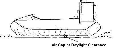
Sketch by J. Benini
Pressure is defined as
the force exerted on a surface per unit area of the surface.
Pressure = Force ÷ Area
P = F ÷ A
In order to calculate the lift force of a hovercraft, we solve
this equation for the force.
F = P · A
The lift force is therefore the air pressure inside the
air cushion multiplied by the area enclosed by the hovercraft skirts.
Example:
A typical pressure inside the air cushion of a Discover Hover One
hovercraft is roughly 7 pounds per square foot, or 7 lbs / ft2 [335 N
/ m2]. If the hovercraft is 10 ft [3 m] long and 5 ft [1.5
m] wide, what is the total lift force produced by this hovercraft?
Solution:
First we must calculate the area of the hovercraft. This is done by multiplying
the length times the width. The solution will be worked out in both Imperial
and System International units.
|
Imperial Units
Area = Length · Width
Area = (10 ft)(5 ft)
Area = 50 ft2
|
S I Units
Area = Length · Width
Area = (3 m)(1.5 m)
Area = 4.5 m2
|
Now we can find the lift force by multiplying the pressure times the
area.
|
Lift force = Pressure · Area
Lift force = (7 lbs / ft2)(50 ft2)
Lift force = 350 lb
|
Lift force = Pressure · Area
Lift force = (335 N / m2)(4.5 m2)
Lift force = 1508 N
|
This hovercraft produces 350 lb [1508 N] of lift force and will therefore
be able to support up to 350 lb [1508 N] of total weight and still hover.
This means if the actual hovercraft weighed 100 lb [444.8 N], then it
could carry 250 lb [1112 N] of people and cargo.
|
In the case of hovercraft, there are two forms of pressure that can be measured:
static pressure and dynamic pressure. Static pressure is the pressure of a stationary
region of air, while dynamic pressure is the pressure of air that is in motion.
Static pressure is what lifts the hovercraft. If you measure the pressure of
the lift air cushion by placing a manometer (a device that measures pressure)
just under the skirt, you will obtain a different value than if you were to
measure the pressure further inside the cushion. This is because the air is
moving rapidly out of the bottom of the skirt, so you could be measuring dynamic
and static pressure at the same time. At the cushion center, the lift air is
more static.
The Discover Hover One hovercraft is an integrated hovercraft. Only one propeller
is used to provide both lift and thrust air. Other hovercraft designs have separate
lift and thrust systems. The sole purpose of the fan is to maintain the pressure
inside the air cushion under the hovercraft. A multi-bladed fan is used for
lift because it's better (more efficient) at pumping pressure than a propeller
with just two blades. A separate propeller mounted on the back of the hovercraft
is responsible for driving the hovercraft forward.
Integrated type
Separate
lift and thrust systems
Sketch by
J. Benini
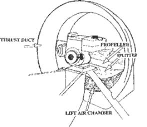
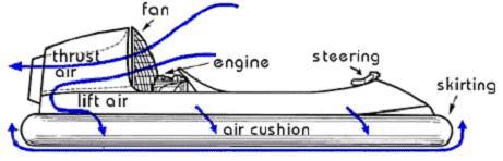
In the integrated hovercraft, the lift air is divided by a splitter usually
located at the bottom of the thrust duct, as shown above. By placing this splitter
just after the propeller, a portion (usually 1/3 of the total air supply) is
forced by the propeller and directed down into the air cushion by the splitter
in order to maintain the pressure inside the cushion. The rest of the air is
forced behind the hovercraft, propelling the hovercraft forward. A diagram of
the various paths the intake air travels in an integrated type of hovercraft
is shown below.
Sketch by
J. Benini
Continue to Experiment
4.1